This follows on from a separate page with an overview of my kit for making PCB271- Morse Code Reader.
It is also the target of pages selling the board as a general purpose breakout for any ATtiny85 (or similar) chip. If you just want the bare PCB, skip the rest of this page, contact me, tell me what country you're in (postage issues) and I will get back to you. (I'm "just" a hobbyist, but the unpopulated PCB is manufactured by a commercial firm- high quality.)
What is meant here by "Morse Code Reader?
It is a small gizmo with some sort of "doorbell" (momentary) switch, which can "translate" Morse code, as input via a momentary switch, into ordinary characters, and send serial data elsewhere, so the characters are displayed somehow. (See overview page, if you got here but are not yet convinced you want my Morse Code Reader. The hard part, the software, was written by Edgar Bonet. (The link takes you to the same place as the link in the previous paragraph. It gives you an overview, and important background information.)
If you want to obtain one, you need to be able to do simple soldering. There are no SMT components. You don't need to do any ATtiny programming.
((This is a stub for the "Assembly" section. If you need more help, pester me, and I'll try to find a Round To-It for the job.))
Assembly is pretty straightforward.
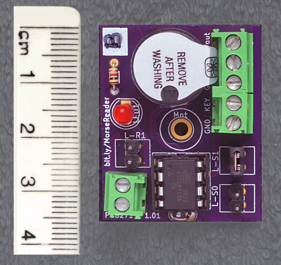
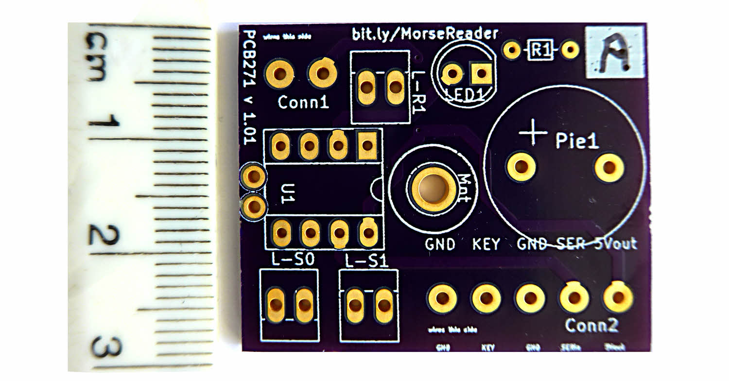
A few components are polarized, i.e. have to "go in" "the right way around". Note in particular that the piezo sounder is one of them. It also pays to put the socket for the ATtiny in carefully... most have a mark to tell you which way the chip should "go". (In the case of this board, the chip's pin 1 should be at the end farthest from the edge of the board.)
The test point near the center of the schematic, with the red blob, is only present from version 1.02 of the board. It is represented on the board by a pad near the LED, on the piezo buzzer side of the LED.
Start by quick checks on the bare board with a multimeter that there are no flaws in the board. You can't test "everything", of course, but at least see that the GND pads connect to each other and nothing else. Ditto the Vcc pads.
As usual, it is best to do the low profile components first.
Assemble everything, but do not, yet, put the ATtiny into its socket.
Between the socket for the ATtiny and the edge of the board, there are two pads, quite close to one another. Solder a loop of wire into these pads, and you have an easy way to clip a multi-meter lead to the GND trace of the circuit.
From vers 1.02, there is a pad near the center of the board that doesn't seem to be "for" anything. This is a place to solder a flying lead to the trace that goes to pin 2, data line "PB3", of the ATtiny. (You don't need to do that for the Morse Reader... it is there for people using the PCB for other things.)
Repeat the multimeter tests. Note that the LED, resistor and piezo sounder are pretty much isolated until the ATtiny is present, though, of course, they connect to GND. But there's no way, other than from pads of the socket, for current to get to ground though them.
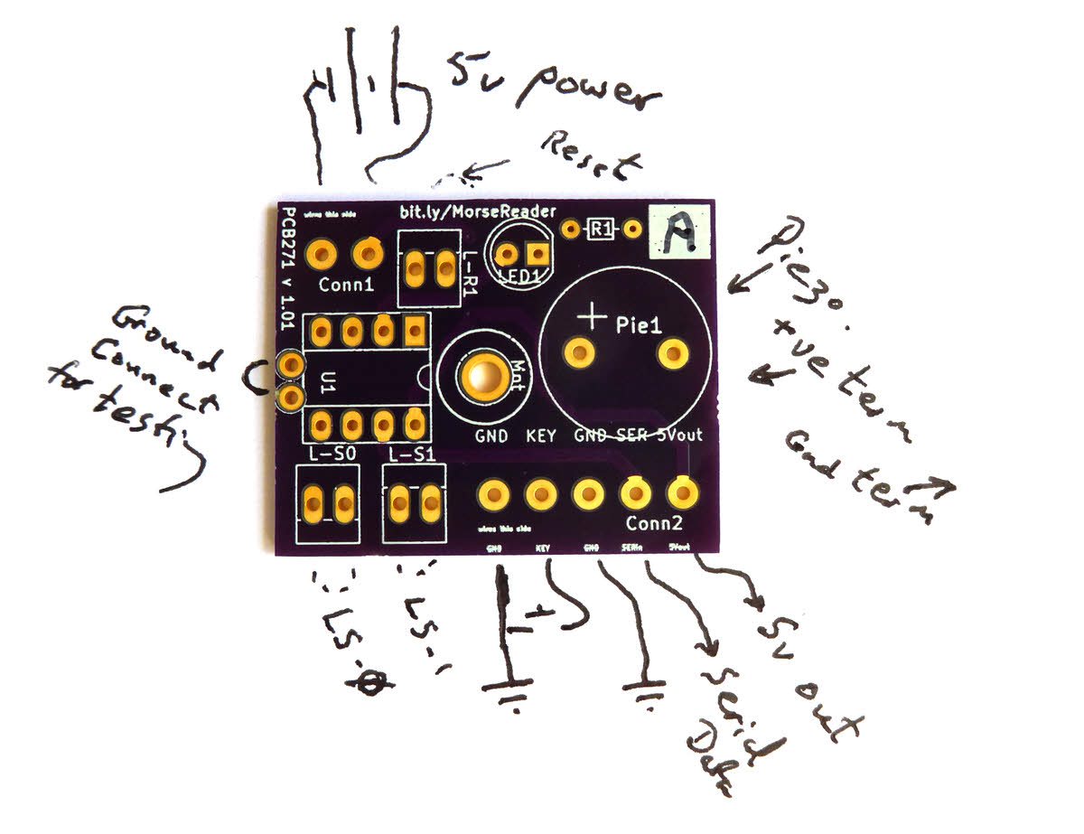
There are two sets of pads on the board, Conn1 (2 pads) and Conn2 (5 pads). Generally speaking, I would recommend fitting them with screw terminals, but of course that is not essential.
You may or may not use all of the connections provided for, depending on how you power your Morse Reader, and what display you use.
This section of this page is to stress something about what I was thinking when I designed the board.
The board must be connected to a source of power, a display (which may need power) and a Morse key.
I wanted to make it easy.
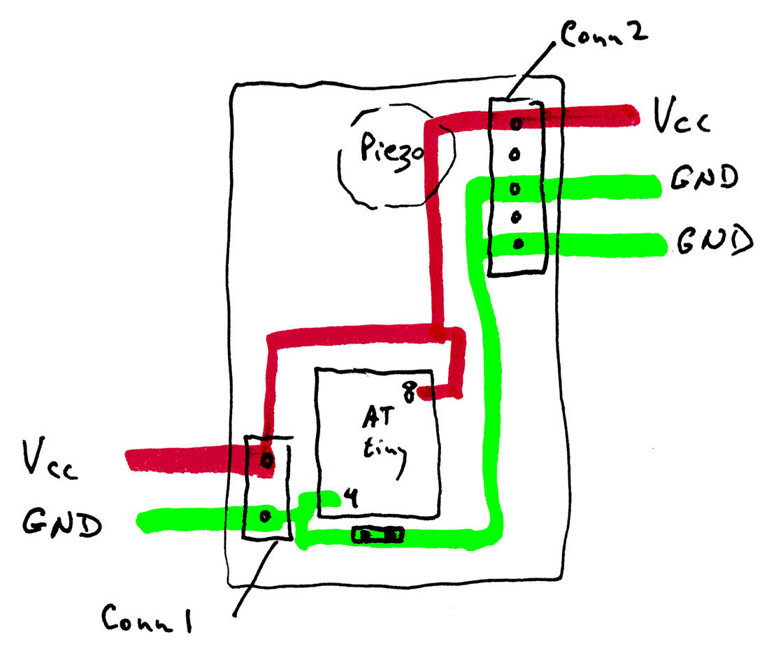
As in all "ordinary" electronics, all parts of the circuit must have their grounds interconnected. All of the three points marked "GND" in PCB271's various diagrams are interconnected. If you want to connect something's ground, you can connect it to the PCB at any of the three easily available places. (Or, if you are "getting fancy", a number of other places, as well, of course.)
The board also has two places marked Vcc. NOTA BENE: You should NOT connect two SOURCES of Vcc to the board. You must connect one source. You can connect it to either of the places marked Vcc. You won't always need the other one. But the only thing you should use it for, if you use it at all, is for passing the source of power on to some other part of the overall system. If you use the second place for connecting Vcc, it would probably be going to the Vcc INPUT of your display device.
Having got this far, you can't put off the evil moment much longer. Insert ATtiny.
Connect the board to your supply's GND line. Prepare connect Vcc.
When you connect Vcc, don't be alarmed... in fact, be pleased!... if the piezo sounds. You should get a "dit- dah- dit". This tells you it is working! You'll get it again each time you reset the ATtiny.
When you first connect Vcc, be ready to snatch the wire away of "odd" things happen.
Assuming "odd things" didn't happen...
Connect the switch which is the Morse key. (Or just do something when I say "press key" to short the two pads of the 5-way terminal strip which at the end not near the corner.
Press the key. As long as it is down, the LED should be on, the piezo making noise.
Connect the ground of your display to the ground of the board. The middle pad of the 5-way connector, or the pad near the corner on the 2-way connector are, electronically, indistinguishable.
Connect power to the display.
Connect the data OUT of PCB271 (second pin from one near corner on 5-way connector) to the data IN line for your display. (Be sure you know what you need to about "levels"... if in doubt, as me to clarify.) The display has to be watching for 9600 baud data.
Try pressing the key briefly, with about 2 second pauses between key presses. You should get Es or Ts on the display.
Until that much is working, go back, see if you can find where something's wrong.
So! You've got "E"s or "T"s! Great! Hardware working.
Now you need to learn Morse!
Try sending "SOS". I'll use * for a "dit", - for a dash, from now on.)
"SOS" is *** --- ***... but it isn't that simple!
TIMING matters! A - that is too short is a *!
If you didn't even come close to getting SOS on the display, go back to sending Es (a *) and Ts (a -). Short press: E, long press: T.
Once you can reliably do *** --- ***, you may still fail to get SOS. You have to pause briefly between the *** and the --- and the ***. That pause tells the Reader that a letter has ended. *** PAUSE --- is SOS. * PAUSE * PAUSE * PAUSE - PAUSE is EEET!
You can do this! It is hard to make the pause between the dits and dahs of a letter too short. Make the pause between the dits and dahs of two letters, and you get an inter-word space. I'll write those as "_". So... once you can send "S" and "O" reliably, probably by making a two big pause between the three dits and the three dahs, you'll be getting S_O_S.
But, persevere, be careful with the length of your spaces, and eventually you'll be getting it right to cause "SOS_SOS_SOS..."!
Once you've got that far, you might want to tell the Morse Reader to "work" at a different speed. Sometimes sending very slowly is harder than sending at a medium speed.
Put jumpers on one or both of the "S" links... the pairs of pins, 0.1" apart, marked L-S0 and L-S1 ("Link, speed Select Zero" and "Link-speed Select One")
After you change the state of the links, briefly short the pins of the other pair of pins (L-R1... "Link, Reset"). When you remove the short across those pins, the ATtiny will reset, starting up configured for whatever speed the speed select links are specifying at the time. (Not that the state of the speed select links is only checked as the ATtiny starts up, be it after a reset, or after a power cycle.)
As the ATtiny is starting up, as mentioned, it sends a dit-dah-dit to the piezo, at the speed it will be able to read code. That dit-dah-dit should help you adjust how fast you send the code.
That's about it for "how to run it". Let me know the bits you wanted more help with.

You know E, T, S and O... so you can send, can't you, "TOES". Or, say, "TO SEE TOT SO". (I'm not sure what that means... but it will tax you for a bit. Try it!) Add A (*-), N (-*), R (*_*), and you can manage quite sensible phrases. ("TO SEE A TOE", etc, etc... make up your own!)
Add the following easy to remember, easy to send letters... I (**), H(***) and M (- -). NOW, LOTS of words are possible. Build your speed, add new letters as it takes your fancy.
Some are easy to remember with mnemonics. The code for L is *-** which (say it out loud) "sounds" a bit like "fraternity" (say it in your head, as you say dit dah dit dit out loud). (If you can explain why I can remember that L is fraternity so it is *-** more easily than I can just remember "L: *-**", then you are on your way to a Nobel prize. But just because it can't be explained doesn't mean that it, or similar, works!)
It won't help you use the Morse Reader, but while you're thinking about the whole subject of Morse, read what Wikipedia has to say about why E is dit and Q is dah dah dit dah.
There are a few "expensive" parts that I am happy to put on an "a la carte" menu. Tell me which ones you want.
There are a number of inexpensive parts which I offer in an "all or nothing" goodie bag. (When I have all of them on hand... sometimes the goodie bag is incomplete, but I'll let you know what's missing before sending one like that.)
There would be p&p to add, too, of course...
PCB (PCB271) costs about US$4
Piezo sounder costs about  $3
5 way connector, 0.15" pitch pins: about $1.20
2 way connector, 0.15" pitch pins: about 50 cents
Total cost... US$2 or less...
Socket for ATtiny (8 pin DIL)
Small LED
Suitable resistor for LED, board expects 1/8W form
3x pairs of pins 0.1" pitch
2x Jumper/Linker/Hat to short a pair of the forgoing
If you like the look of the above, contact me for details of the precise current situation. Please use subject line "PCB271 enquiry".
Full details of the software, with note son what hardware it needs at Edgar Bonet's ATtiny Morse Decoder Github page. If you've not used Github before, you just follow that link. You can download a .zip with everything in it (button is at right edge of screen, just above file directory.) There is a LOT of documentation in the "README.MD" file, the contents of which are easily read online, as they appear below the list of the files. That will open to be read in your browser. (If you download it, you can read it with any text editor... but it contains markup codes.)
The repository holds a "bonus item" for anyone undertaking the challenge: auto-test.ino. It is in the Tools directory. It is an Arduino program which sends some Morse and checks whether the ATtiny reports the correct characters. IT could be adapted to send the Morse at different speeds, or to test a different character repertoire.
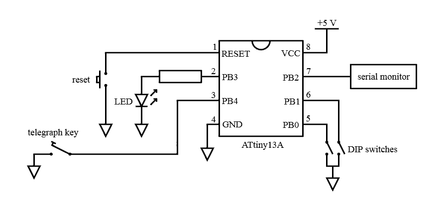
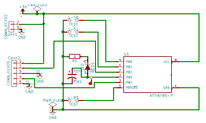
On the left: His circuit, from the Github page, where you'll find much more. He's shown both what's part of PCB271 and the external components. In other words his diagram doesn't differ from mine except in readability and neatness.
That's it, I hope!
Please spread the word?? If you think others would find this page interesting, "http://bit.ly/MorseReader" is a quick way to get to a good starting point!
You are responsible for any consequences of using what is on any of my pages!
Please get in touch if you discover any flaws in the board, or any ways to go wrong. How you are using it would also be of interest.
If you visit 1&1's site from here, it helps me. They host my website, and I wouldn't put this link up for them if I wasn't happy with their service.
Click here to visit editor's Sheepdog Software (tm) freeware, shareware pages.
Click here to visit the homepage of my biggest site.
Click here to visit the homepage of Sheepdogsoftware.co.uk. Apologies if the "?FrmAht" I added to that link causes your browser problems. Please let me know, if so?
![]() Page tested for compliance with INDUSTRY (not MS-only) standards, using the free, publicly accessible validator at validator.w3.org
Page tested for compliance with INDUSTRY (not MS-only) standards, using the free, publicly accessible validator at validator.w3.org
....... P a g e . . . E n d s .....